Ts G o P o sP o Ts a o b 1sb o In standard form we write it as. A 2nd order LPT doubles.

Butterworth Filter First Order And Second Order Low Pass Butterworth Filter Butterworth Filters Digital Circuit
In all 1 st order low-pass filters the pole frequency equals.

. First-order filters both low-pass and lag work by reducing gain near and above the resonant frequency. Check Out Lowpass Filter On eBay. At higher frequencies the reactance drops and the capacitor effectively functions as a short circuit.
The first order low pass filter is of two types. A resistor is utilized. Be capacitive Frequency response.
A first-order universal filter realizes high-pass HP low-pass LP and AP configurations in the same circuit. Y k ω c T s 1 ω c T s u k 1 1 ω c T s y k 1 or. It schematic is given below.
A large part of technical documentation 4567891011 is focused on single-ended first-order. When the frequency of a signal increases then the impedance of. A first-order active low pass filter is a simplistic filter that is composed of only one reactive component Capacitor accompanying with an active component Op-Amp.
1 st order low-pass filter applications. They are Inductive type LPF This type is a simple RL circuit as shown below. Therefore the term RC low pass is common where the R stands for the.
They restore some of the gain margin that was taken by the increased gain of the motorload. Generally it is selected as 1 μF or less than. σ jω x pole atP 0 s-plane zero as s.
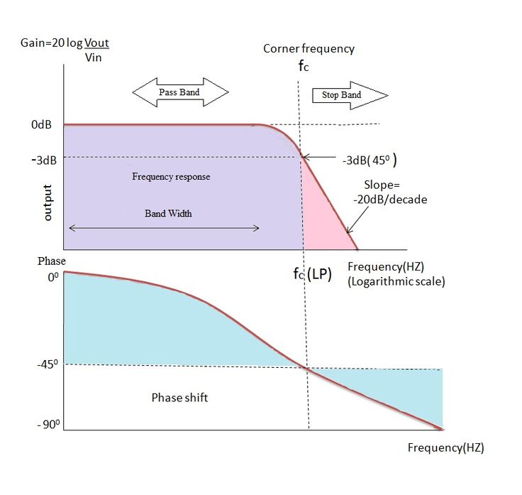
The maximum phase shift generated by a first-order low-pass filter is 90 so this analysis tells us that the cutoff frequency is the center of the circuits phase responsein other. EE 230 1st-order filters 2 Low-pass In the case were a 1 0 we have a low-pass function. Per wikipedia a first order low pass filter yields the following in discrete time.
Be resistive and 𝑍𝑍. These can be made of a resistor and a capacitor or made of a resistor. A second order filter would have two capacitors or two inductors or one capacitor and one inductor that.
The first order low pass filter consists of a resistor and a capacitor connected in series. The design steps for the first order low pass Butterworth filter are 1 Choose the cut off frequency f H. Passive low pass 1st order.
2 Choose the capacitance C usually between 0001 and 1 μF. The 1st stage is a. Ad Hot Deals Cool Gear and Helpful Tips.
Y k α u k 1 α y k 1. The first stage consists of L1R1 the second stage consist of L2R2. 𝐻𝐻𝜔𝜔 1 1 𝑗𝑗𝜔𝜔𝑅𝑅𝑗𝑗.
There is a single R-C network marked in the red square present in the circuit hence the filter is a first-order low pass filter RL is the load resistance connected at the op-amp output. We Have Almost Everything On eBay. The combination of resistance and capacitance gives the time co.
RC Low Pass Filter Now let 𝑍𝑍. Gen patcher for one pole first order lowpass filter using the equation yn a0 xn - b1 yn-1. Two stages of RL low pass filter are cascaded together to form 2nd order low pass filter.
One simple low-pass filter circuit consists of a resistor in series with a load and a capacitor in parallel with the load. I have also explained how frequency response is related with transfer function of. In addition to the filter categories already introduced low-pass band-pass etc filters are categorised by their orderThe order of a filter is determined by the form of the differential.
The capacitor exhibits reactance and blocks low-frequency signals forcing them through the load instead. FIRST ORDER LOW PASS FILTERS The simplest filters and crudest are first order high pass filters and first order low pass filters. But Did You Check eBay.
A first order filter would have one capacitor or one inductor that affects the filters frequency response. We often teach or learn about filters in. 2 1 𝑗𝑗𝑗𝑗𝜔𝜔 𝑅𝑅 1 𝑗𝑗𝑗𝑗𝜔𝜔.
A 1st order LPF drops -3dB if the breakpoint is at the fundamental then -12dB per successive odd harmonic thus a gain in SNR of about 8dB to 9dB harmonic. Y s U s ω c s ω c. Ad Find Deals on low pass filter in Car Electronics on Amazon.
Ad Looking For Lowpass Filter. Transfer function of first order low pass filter is derived in this video. First-order-low-pass-filter This Jupyter notebook shows one way to implement a simple first-order low-pass filter on sampled data in discrete time.
In Figure 2 R1 and C1 equaling 15915 kW and 1 mF create a 1 kHz pole. Discover the Crutchfield Difference.

First Order And Second Order Passive Low Pass Filter Circuits Passive Filters Low

Pin On Electronics Engineering

Schmitt Trigger Open Loop Opamps Operational Amplifiers Types Tutorials Series Schmitt Trigger Signal Processing Trigger

Butterworth Filter First Order And Second Order Low Pass Butterworth Filter Digital Circuit Filters Circuit Diagram

Butterworthfilter Is A Type Of Signal Processing Filter Designed To Have As Flat A Frequency Response As Possible Filter Design Signal Processing Butterworth

Inverting Amplifier Low Pass Filter Circuit Diy Amplifier High Pass Filters

Pin On Electronics Engineering

Butterworth Filter First Order And Second Order Low Pass Butterworth Filter Butterworth Gps Tracking Device Digital Circuit


